Make your own home-made CNC machine
Create your own home made CNC by eng Mohammad SAFEEA
Control and electrical Systems:
1- LPT port:
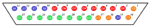
First of all we will make a review of LPT port, because it will be the gate that connects our contol mind on one hand and the motors and laser on the other hand, the LPT port is 25 pin port as shown in the picture below.
The port IO pins are deivided into four groups which are named D, C, S and G.
D from D0 to D7, bidirectional which can be used as inpots or outpots in other words you can either write to it or read from it.
C from C0 to C3 could be used only as outpots, and note here that C2 is inverted so if you write one to it output will be zero, on the overhand if you write zero to it you will have an output voltage "5volt'.
S from S3 to S6 could be only used as an inpots.
G from G0 to G7 are the ground 0 Volt.
Now after getting an Idea about LPT port, we will learn how to connect it to the Laser CNC machine but first we will learn what kind of signals the machine needs inorder to function, the machine have the following electrical components:
1- X and Y stepper motors used to drive the cutting head
2- The laser power unit, which is used to power the laser and to contol its outpot energy.
3- We have the homing sensors for each of X and Y axis
So the LPT port has to be connected in some way to each of the aforementioned components.
1- Connecting LPT port to the Stepper motors:
We have two stepper motors each stepper motor needs two signals to funcion, the pulse signal and the direction signal.
We will use C0 as the pulse outpot, and C1 as the direction outpot, so you need to wires to connect C0 and C1 from the LPT port to the pulse and direction inpots of X stepper-motor-driver.
In the same way C2 and C3, represents the pulse and the direction for Y axis stepper motor, and they should be wired to their correspondings on the motor-driver side.
2- Connecting LPT port to laser power unit:
In-order for the laser tube to operate it sould be powered by high voltage power unit, the outpot of the power unit can be controlled using an analog input, the input can handle 0 to 5 volt electrical signal and the laser's beam-power will be prportional to the input signal, so we need to use eight bit digital to analgue converter, the digital input of the converter will be wired to pins D0 to D7 from LPT port.
And the output of the converter will be wired to the input control signal of laser power unit.
3- connecting homing sensors to LPT port:
You can use the mechanical sensors "cheaper and easier for installation" and they are more than enough for our application, in this case one side of the sensor will be connected to 5volt the other side will be connected to S0 if X-axis homing sensor or S1 if Y-axis homing sensor.
And this is pretty much the connection work between the computer and the machine for the laser cutting CNC.
4- Then you can download my NC program, and install it on your computer, or your can use mach3 program for controlling your machine:
As we said the controlling mind of the machine will be your desktop computer, but first you have to install an motion control software on it.
You can use my program that I wrote when I was in college, or you can use mach3 program.
The offecial website for mach3 is: http://www.machsupport.com/
Or you can contact me via email, I will send you my program for free: ronnie555to666@gmail.com
Right now I will explain how to connect the electrical system:
It is also so simple, as we said before the electrical systems is comprised of two stepper motors to drive the axes and the laser generator.
1- connecting laser generator:
Laser generator is constitutes of three units, Co2 laser tube, laser power unit, cooling system.
The laser power unit have one output "2 high voltage wires" and shall be connected to the electrodes of laser-tube.
The input of the laser power five inputs, one of them is the ground, another shall be connected to 5 volts power supply theird shall be connected to the ground and fourth is for controlling the laser's output-power, the fifth leave it un-connected.
Why is the fifth? if you are curious about it here is the answer, generally laser power supplies can be controlled by two means one by using analog signal the other by using "pulse width modulation" PWM signal, so if you like you can use a microcontroller to generate PWM signal for controlling the laser instead of the analog signal, its your call.
2- Connecting stepper motors, and their drivers:
The driver have some inputs and some other outputs, the outputs shall be connected to the stepper motor:
There are several types of stepper motors bipolars "with 4 leads", or Unipolar "6 or 8 leads" whcih also could be connected in a way to be analoguos to the bipolar, follow the instructions of your driver's manual when to connect the motor to the driver.
The inputs are isolated using photo-couplers, there is one for pulse and other for direcion, there is a third input and which is used to cut power from the motor when activated, leave it un-connected, and finallay there is the power input, according to your driver you may connect it directly to the grid or it may require you to buy a AC to DC transformer.
4- Connecting the cooling system:
The laser tube has to be cooled inorder to prevent it from over heating and damage, the method of cooling is by using water cooling system, it is very easy to connect it, you have to connect the laser tube to the cooler using rubber tubes, after that plug the cooler to the grid, just that simple, you can connect the cooling system to the machine main cercuit breaker so when you turn the machine on the cooling system starts to work automatically.
.